
Construcción de poliimida para interconexiones compactas, móviles o limitadas. Ventana de proceso verificada: Flex layers: Up to 12 layers; Flex thickness: 0.1–1.0 mm; Flex materials: SHENGYI · Pyralux® KP · Panasonic Archivos para revisión: Gerber u ODB++, archivos de taladro, stackup, plano, cantidad y fecha objetivo. Los límites publicados proceden de la tabla actual de capacidades de JETFGO. La viabilidad final requiere el paquete completo.
Los límites publicados proceden de la tabla actual de capacidades de JETFGO. La viabilidad final requiere el paquete completo.Código de soluciónFLEX-MLCapacidad verificada
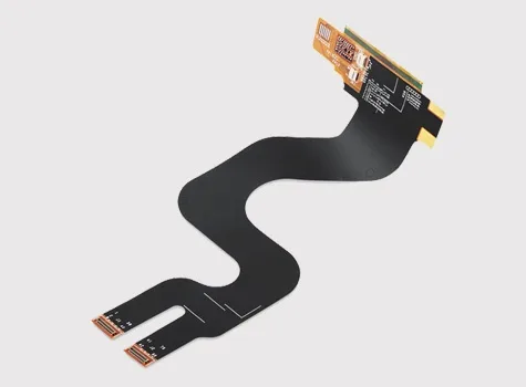
PCB flexible multicapa
Construcción de poliimida para interconexiones compactas, móviles o limitadas.
JETFGO / FLEX-MLFLEX
01 / RESPUESTA TÉCNICA
Respuesta técnica
02 / DATA
Ventana de proceso verificada
Construcción de poliimida para interconexiones compactas, móviles o limitadas.
Flex Layer Capability
Up to 12 layers
Flex Thickness Range
0.1–1.0 mm
Flex Material Options
SHENGYI · Pyralux® KP · Panasonic
Flex Application
Static or dynamic use, subject to project review
Flex-Zone Review
Bend area · routing direction · coverlay · stiffener
Engineering Review
Stack-up · copper structure · bend requirements · assembly interface
05 / INPUT
Archivos para revisión
Flex PCB Engineering Package
Gerber or ODB++, drill files, proposed stack-up, fabrication drawing, quantity, target delivery date and any defined bend, flex-zone, coverlay or stiffener requirements.
Flex Stack-up Requirements
Provide the proposed layer structure, flex thickness, copper weights, polyimide material requirements and any adhesive or coverlay specifications when available.
Bend & Flex-Zone Requirements
Identify static or dynamic use, bend locations, available bend radius, movement direction and any restricted component or plated-feature areas.
Stiffener & Assembly Requirements
Solicitar cotizaciónProvide stiffener locations, connector or component areas, assembly interfaces and any thickness requirements at reinforced sections.
06 / FAQ
Preguntas técnicas
Los límites publicados proceden de la tabla actual de capacidades de JETFGO. La viabilidad final requiere el paquete completo.
01What is a multilayer flexible PCB?+
A multilayer flexible PCB contains multiple conductive layers within a flexible polyimide-based structure, providing greater routing density while allowing the circuit to bend, fold or fit into compact assemblies.
02Which files help JETFGO review a multilayer flex PCB fastest?+
Send Gerber or ODB++, drill files, proposed stack-up, fabrication drawing, quantity, target delivery date and any defined bend, flex-zone, coverlay, stiffener or assembly requirements.
03Can JETFGO support prototypes and repeat production for multilayer flexible PCBs?+
Yes. Once the flex stack-up, materials, bend requirements and manufacturing conditions are confirmed, the approved engineering record can support prototype validation and repeat production under the same process conditions.
04What is the difference between a flexible PCB and a rigid-flex PCB?+
A flexible PCB uses flexible circuit construction throughout the relevant board area, while a rigid-flex PCB permanently combines rigid PCB sections and flexible interconnect sections within one integrated structure.
05Can multilayer flexible PCBs be used for dynamic bending?+
They can be evaluated for dynamic-flex applications, but final suitability depends on the flex stack-up, copper construction, bend radius, conductor routing, flex length and required movement cycle.
06What information is needed to define a flex PCB bend area?+
Provide the bend location, available bend radius, static or dynamic use, movement direction, flex-zone length and any restrictions on components, vias or plated features in the bending area.
07What are stiffeners used for on a flexible PCB?+
Stiffeners reinforce selected flex PCB areas such as connectors, component locations or assembly interfaces where additional mechanical support or controlled thickness is required.
08Does a higher flex layer count affect bending performance?+
Yes. Increasing the number of conductive and dielectric layers generally increases the mechanical complexity of the flex structure, so bend performance must be reviewed together with total thickness, copper construction and intended movement.
RFQ / DFM
Envíe el requisito. Reciba un plan de suministro fabricable.
Envíe Gerber u ODB++, stackup, material, cantidad, fecha objetivo y pruebas para revisar la viabilidad y cotizar.
Revisión técnicaMaterial y stackupFabricación precisa