
Revisión de stackup, planos de referencia y back-drill para placas de datos. Ventana de proceso verificada: Impedance tolerance: ±8%; Back drilling: Any-layer capability; Mechanical aspect ratio: Up to 20:1 Archivos para revisión: Gerber u ODB++, archivos de taladro, stackup, plano, cantidad y fecha objetivo. Los límites publicados proceden de la tabla actual de capacidades de JETFGO. La viabilidad final requiere el paquete completo.
Los límites publicados proceden de la tabla actual de capacidades de JETFGO. La viabilidad final requiere el paquete completo.Código de soluciónHS-06LCapacidad verificada
PCB high-speed de 6 capas
Revisión de stackup, planos de referencia y back-drill para placas de datos.
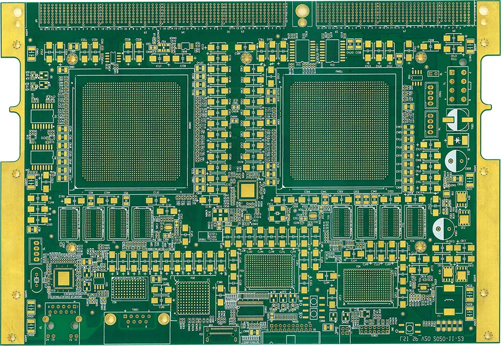
JETFGO / HS-06LRIGID
01 / RESPUESTA TÉCNICA
Respuesta técnica
02 / DATA
Ventana de proceso verificada
Revisión de stackup, planos de referencia y back-drill para placas de datos.
Impedance Tolerance
±8%
Back Drilling
Target-layer and depth review based on stack-up
Mechanical Aspect Ratio
Up to 20:1
High-Speed Stack-up
Reference-plane and controlled-impedance review
Back-Drill Review
Drill side · target layer · residual stub · depth
05 / INPUT
Archivos para revisión
High-Speed PCB Engineering Package
Gerber or ODB++, drill files, proposed stack-up, fabrication drawing, quantity, target delivery date and applicable controlled-impedance or back-drill requirements.
Controlled-Impedance Requirements
Provide target impedance, tolerance, routing layer, reference plane and applicable single-ended or differential signal classes.
Back-Drill Requirements
Provide the required drill side, target layer, residual stub requirement and any project-specific back-drill depth or tolerance information.
High-Speed Stack-up
Solicitar cotizaciónProvide the proposed layer order, signal layers, reference planes, board thickness, copper requirements and material preferences when available.
06 / FAQ
Preguntas técnicas
Los límites publicados proceden de la tabla actual de capacidades de JETFGO. La viabilidad final requiere el paquete completo.
01Is ±8% impedance tolerance guaranteed for every 6-layer high-speed PCB?+
No. ±8% is a published capability reference for this solution. Final impedance feasibility depends on the complete stack-up, materials, dielectric structure, copper thickness, trace geometry and target impedance confirmed during engineering review.
02Which files help JETFGO review a 6-layer high-speed PCB fastest?+
Send Gerber or ODB++, drill files, proposed stack-up, fabrication drawing, quantity, target delivery date and any controlled-impedance or back-drill requirements.
03Can JETFGO support prototypes and repeat production for 6-layer high-speed PCBs?+
Yes. Once the stack-up, materials, impedance requirements and back-drill conditions are confirmed, the approved engineering record can support prototype validation and repeat production under the same manufacturing conditions.
04Why is stack-up important for a 6-layer high-speed PCB?+
The stack-up defines the relationship between signal layers, reference planes, dielectric thickness and copper geometry. These factors directly affect controlled impedance, return-current paths and high-speed signal integrity.
05When is back drilling needed on a high-speed PCB?+
Back drilling may be considered when unused plated-through-hole stubs could affect high-speed signal integrity. Final need and drill depth depend on the signal requirements, stack-up, via transitions and acceptable residual stub.
06What is a via stub in a high-speed PCB?+
A via stub is the unused conductive portion of a plated through-hole beyond the signal connection layer. At high data rates, it can contribute to reflections and impedance discontinuities, so selected vias may require back drilling.
07Can a 6-layer PCB support both single-ended and differential impedance?+
Yes. A 6-layer PCB can support single-ended and differential controlled-impedance signals when the stack-up, routing layers, reference planes and trace geometry are designed appropriately and confirmed during engineering review.
RFQ / DFM
Envíe el requisito. Reciba un plan de suministro fabricable.
Envíe Gerber u ODB++, stackup, material, cantidad, fecha objetivo y pruebas para revisar la viabilidad y cotizar.
Revisión técnicaMaterial y stackupFabricación precisa