
Integrierte starre und flexible Bereiche für kompakte Baugruppen mit weniger Steckern. Bestätigtes Prozessfenster: Flex capability: Up to 12 layers; Blind / laser via: 3–5 mil; IPC class: Class 2 and Class 3 Daten für die Prüfung: Gerber oder ODB++, Bohrdaten, Stack-up, Fertigungszeichnung, Menge und Zieltermin. Die veröffentlichten Grenzen stammen aus der aktuellen JETFGO-Fähigkeitsmatrix. Die endgültige Machbarkeit erfordert vollständige Daten.
Die veröffentlichten Grenzen stammen aus der aktuellen JETFGO-Fähigkeitsmatrix. Die endgültige Machbarkeit erfordert vollständige Daten.LösungscodeRFX-06LFähigkeit belegt
6-Lagen-Rigid-Flex-PCB
Integrierte starre und flexible Bereiche für kompakte Baugruppen mit weniger Steckern.
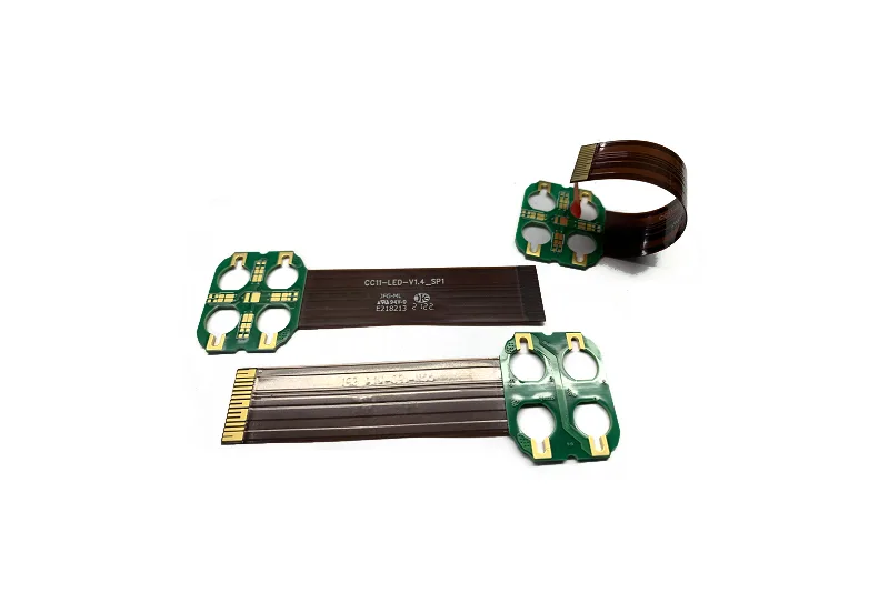
JETFGO / RFX-06LRIGID-FLEX
01 / TECHNISCHE ANTWORT
Technische Antwort
02 / DATA
Bestätigtes Prozessfenster
Integrierte starre und flexible Bereiche für kompakte Baugruppen mit weniger Steckern.
Flex Layer Capability
Up to 12 layers
Blind / Laser Microvia
3–5 mil
IPC Workmanship Class
Class 2 and Class 3, subject to project requirements
Rigid-Flex Structure
Integrated rigid regions · flexible interconnect zones
Flex-Zone Review
Bend area · transition · coverlay · stiffener · copper routing
Engineering Review
Stack-up · via structure · bend requirements · assembly interface
05 / INPUT
Daten für die Prüfung
Rigid-Flex Engineering Package
Gerber or ODB++, drill files, proposed rigid-flex stack-up, fabrication drawing, quantity, target delivery date and any bend, flex-zone, via, coverlay, stiffener or IPC-class requirements.
Rigid-Flex Stack-up Requirements
Provide the rigid and flex layer structure, board thicknesses, flex thickness, copper weights, polyimide material requirements and layer-transition information.
Bend & Flex-Zone Requirements
Identify bend locations, available bend radius, static or dynamic use, flex-zone length, movement direction and any restricted component or via areas.
Transition & Reinforcement Requirements
Provide rigid-to-flex transition locations, coverlay requirements, stiffener locations, connector interfaces and any mechanical reinforcement requirements.
IPC & Reliability Requirements
Angebot anfordernSpecify the required IPC workmanship class, inspection criteria and any project-specific reliability, qualification or documentation requirements.
06 / FAQ
Technische Fragen
Die veröffentlichten Grenzen stammen aus der aktuellen JETFGO-Fähigkeitsmatrix. Die endgültige Machbarkeit erfordert vollständige Daten.
01What is a 6-layer rigid-flex PCB?+
A 6-layer rigid-flex PCB combines rigid PCB regions and flexible interconnect sections within one integrated circuit structure. It can reduce connectors and cable assemblies while supporting compact packaging and controlled flex routing.
02Which files help JETFGO review a 6-layer rigid-flex PCB fastest?+
Send Gerber or ODB++, drill files, proposed rigid-flex stack-up, fabrication drawing, quantity, target delivery date and any bend, flex-zone, via, coverlay, stiffener or IPC-class requirements.
03Can JETFGO support prototypes and repeat production for rigid-flex PCBs?+
Yes. Once the rigid-flex stack-up, materials, via structure, bend requirements and manufacturing conditions are confirmed, the approved engineering record can support prototype validation and repeat production.
04What is the difference between rigid-flex PCB and flexible PCB?+
A flexible PCB primarily uses flexible circuit construction, while a rigid-flex PCB permanently combines rigid PCB sections and flexible interconnect sections within the same integrated board structure.
05Why use a rigid-flex PCB instead of separate PCBs and cables?+
Rigid-flex construction can reduce connectors, cables and separate interconnect assemblies while improving packaging efficiency. Final benefits depend on the mechanical, electrical and assembly requirements of the product.
06Can blind or laser microvias be used in a rigid-flex PCB?+
Yes. Blind and laser-drilled microvias can be evaluated for rigid-flex designs when higher routing density is required. Final feasibility depends on the layer structure, via location, transition regions and complete manufacturing stack-up.
07Can JETFGO manufacture rigid-flex PCBs to IPC Class 3 requirements?+
JETFGO can review rigid-flex projects requiring IPC Class 2 or Class 3 workmanship. Final process controls, inspection requirements and qualification conditions are confirmed according to the complete project specification.
08What should be considered in the rigid-to-flex transition area?+
The transition area should be reviewed for copper routing, dielectric changes, coverlay, bend location, via placement, mechanical stress and component clearance to reduce reliability risks during assembly and use.
RFQ / DFM
Anforderung senden. Einen fertigbaren Lieferplan erhalten.
Senden Sie Gerber oder ODB++, Aufbau, Material, Menge, Zieltermin und Prüfanforderungen für Machbarkeitsprüfung und Angebot.
Engineering-PrüfungMaterial & Stack-upPräzisionsfertigung