
커넥터를 줄이고 전이 영역을 제어하는 통합 리지드 플렉스 구조. 검증된 공정 범위: Flex capability: Up to 12 layers; Blind / laser via: 3–5 mil; IPC class: Class 2 and Class 3 검토용 파일: Gerber 또는 ODB++, 드릴 파일, 스택업, 제작 도면, 수량 및 목표 일정. 게시된 한계는 JETFGO의 현재 공정 능력표를 기반으로 하며 최종 가능성은 전체 자료 검토 후 확정됩니다.
게시된 한계는 JETFGO의 현재 공정 능력표를 기반으로 하며 최종 가능성은 전체 자료 검토 후 확정됩니다.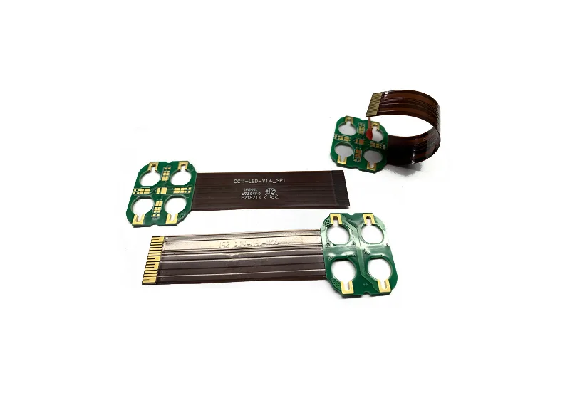
JETFGO / RFX-06LRIGID-FLEX
01 / 엔지니어링 답변
엔지니어링 답변
02 / DATA
검증된 공정 범위
커넥터를 줄이고 전이 영역을 제어하는 통합 리지드 플렉스 구조.
Flex Layer Capability
Up to 12 layers
Blind / Laser Microvia
3–5 mil
IPC Workmanship Class
Class 2 and Class 3, subject to project requirements
Rigid-Flex Structure
Integrated rigid regions · flexible interconnect zones
Flex-Zone Review
Bend area · transition · coverlay · stiffener · copper routing
Engineering Review
Stack-up · via structure · bend requirements · assembly interface
05 / INPUT
검토용 파일
Rigid-Flex Engineering Package
Gerber or ODB++, drill files, proposed rigid-flex stack-up, fabrication drawing, quantity, target delivery date and any bend, flex-zone, via, coverlay, stiffener or IPC-class requirements.
Rigid-Flex Stack-up Requirements
Provide the rigid and flex layer structure, board thicknesses, flex thickness, copper weights, polyimide material requirements and layer-transition information.
Bend & Flex-Zone Requirements
Identify bend locations, available bend radius, static or dynamic use, flex-zone length, movement direction and any restricted component or via areas.
Transition & Reinforcement Requirements
Provide rigid-to-flex transition locations, coverlay requirements, stiffener locations, connector interfaces and any mechanical reinforcement requirements.
IPC & Reliability Requirements
견적 요청Specify the required IPC workmanship class, inspection criteria and any project-specific reliability, qualification or documentation requirements.
06 / FAQ
기술 질문
게시된 한계는 JETFGO의 현재 공정 능력표를 기반으로 하며 최종 가능성은 전체 자료 검토 후 확정됩니다.
01What is a 6-layer rigid-flex PCB?+
A 6-layer rigid-flex PCB combines rigid PCB regions and flexible interconnect sections within one integrated circuit structure. It can reduce connectors and cable assemblies while supporting compact packaging and controlled flex routing.
02Which files help JETFGO review a 6-layer rigid-flex PCB fastest?+
Send Gerber or ODB++, drill files, proposed rigid-flex stack-up, fabrication drawing, quantity, target delivery date and any bend, flex-zone, via, coverlay, stiffener or IPC-class requirements.
03Can JETFGO support prototypes and repeat production for rigid-flex PCBs?+
Yes. Once the rigid-flex stack-up, materials, via structure, bend requirements and manufacturing conditions are confirmed, the approved engineering record can support prototype validation and repeat production.
04What is the difference between rigid-flex PCB and flexible PCB?+
A flexible PCB primarily uses flexible circuit construction, while a rigid-flex PCB permanently combines rigid PCB sections and flexible interconnect sections within the same integrated board structure.
05Why use a rigid-flex PCB instead of separate PCBs and cables?+
Rigid-flex construction can reduce connectors, cables and separate interconnect assemblies while improving packaging efficiency. Final benefits depend on the mechanical, electrical and assembly requirements of the product.
06Can blind or laser microvias be used in a rigid-flex PCB?+
Yes. Blind and laser-drilled microvias can be evaluated for rigid-flex designs when higher routing density is required. Final feasibility depends on the layer structure, via location, transition regions and complete manufacturing stack-up.
07Can JETFGO manufacture rigid-flex PCBs to IPC Class 3 requirements?+
JETFGO can review rigid-flex projects requiring IPC Class 2 or Class 3 workmanship. Final process controls, inspection requirements and qualification conditions are confirmed according to the complete project specification.
08What should be considered in the rigid-to-flex transition area?+
The transition area should be reviewed for copper routing, dielectric changes, coverlay, bend location, via placement, mechanical stress and component clearance to reduce reliability risks during assembly and use.
RFQ / DFM
요구사항을 보내고 실행 가능한 공급 계획을 받으세요.
Gerber 또는 ODB++, 적층, 재료, 수량, 목표 일정과 검사 요구를 보내주시면 기술 검토 후 견적합니다.
기술 검토소재·스택업정밀 제조