
Ruta HDI para diseños compactos, BGA de paso fino y microvías láser. Ventana de proceso verificada: Blind via: 3–5 mil; Laser drill: 3–5 mil; BGA pitch: 0.4 mm Archivos para revisión: Gerber u ODB++, archivos de taladro, stackup, plano, cantidad y fecha objetivo. Los límites publicados proceden de la tabla actual de capacidades de JETFGO. La viabilidad final requiere el paquete completo.
Los límites publicados proceden de la tabla actual de capacidades de JETFGO. La viabilidad final requiere el paquete completo.Código de soluciónHDI-1N1Capacidad verificada
PCB HDI microvía 1+N+1
Ruta HDI para diseños compactos, BGA de paso fino y microvías láser.
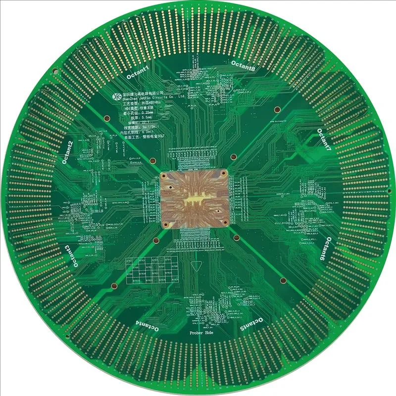
JETFGO / HDI-1N1RIGID
01 / RESPUESTA TÉCNICA
Respuesta técnica
02 / DATA
Ventana de proceso verificada
Ruta HDI para diseños compactos, BGA de paso fino y microvías láser.
HDI Build-Up
1+N+1 sequential lamination
Laser Microvia
3–5 mil
BGA Pitch
0.4 mm, subject to fan-out and DFM review
Microvia Structure
Laser-drilled blind microvia
HDI Process
Sequential lamination · laser drilling
Design Review
BGA fan-out · via-in-pad · microvia geometry · stack-up
05 / INPUT
Archivos para revisión
HDI Engineering Review Package
Gerber or ODB++, drill files, proposed stack-up, fabrication drawing, quantity, target delivery date and applicable microvia, BGA or via-in-pad requirements.
HDI Stack-up & Via Structure
Provide the proposed 1+N+1 layer structure, microvia layer pairs, dielectric thicknesses and any stacked, staggered or via-in-pad requirements.
BGA Fan-Out Requirements
Provide fine-pitch BGA locations, package pitch, pad geometry and any required via-in-pad or escape-routing constraints that may affect the HDI build-up.
Material & Thickness Requirements
Solicitar cotizaciónProvide the preferred PCB thickness, copper weight, laminate or Tg requirements and any dielectric constraints relevant to the HDI stack-up.
06 / FAQ
Preguntas técnicas
Los límites publicados proceden de la tabla actual de capacidades de JETFGO. La viabilidad final requiere el paquete completo.
01Is 1+N+1 HDI suitable for every fine-pitch BGA design?+
No. 1+N+1 is a common HDI structure, but final suitability depends on BGA pitch, pad geometry, escape routing, microvia structure, stack-up and required routing density. More complex designs may require additional build-up layers.
02Which files help JETFGO review a 1+N+1 HDI PCB fastest?+
Send Gerber or ODB++, drill files, proposed stack-up, fabrication drawing, quantity, target delivery date and any microvia, BGA fan-out or via-in-pad requirements.
03Can JETFGO support prototypes and repeat production for 1+N+1 HDI PCBs?+
Yes. Once the HDI stack-up, microvia structure, materials and engineering requirements are confirmed, the approved manufacturing data can support prototype validation and repeat production under the same process conditions.
04What does 1+N+1 mean in an HDI PCB stack-up?+
1+N+1 describes an HDI construction with one build-up layer on each side of an N-layer core. Laser-drilled microvias connect the outer build-up layers to adjacent inner layers.
05What is a laser microvia in an HDI PCB?+
A laser microvia is a small laser-drilled interconnect used to connect adjacent PCB layers in an HDI structure. It enables higher routing density than conventional plated through-hole routing.
06Can JETFGO evaluate 0.4 mm BGA designs for 1+N+1 HDI?+
Yes. JETFGO can evaluate 0.4 mm BGA designs, but final feasibility depends on pad geometry, fan-out strategy, microvia size, via-in-pad requirements and the complete PCB stack-up.
07Does 1+N+1 HDI require sequential lamination?+
Yes. A 1+N+1 HDI structure uses build-up layers added around the core, so sequential lamination and laser-drilled microvias are part of the manufacturing process.
RFQ / DFM
Envíe el requisito. Reciba un plan de suministro fabricable.
Envíe Gerber u ODB++, stackup, material, cantidad, fecha objetivo y pruebas para revisar la viabilidad y cotizar.
Revisión técnicaMaterial y stackupFabricación precisa