
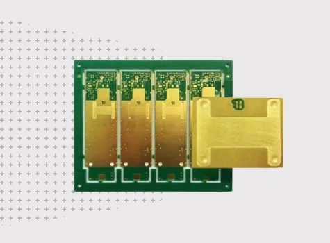
A heavy-copper power PCB uses increased copper thickness in selected or multiple conductive layers to support higher current, improve thermal distribution and strengthen power paths in demanding electronic systems. Heavy copper construction is commonly used in power conversion, motor drives, renewable-energy systems, automotive electronics and industrial control where current-carrying capability, voltage distribution and thermal performance are critical to the board design. JETFGO reviews the complete PCB stack-up together with copper weight, trace geometry, spacing, current paths, thermal requirements, via structures and board thickness before confirming manufacturability. Our published manufacturing capability reference includes rigid inner and outer copper from 1/3 oz up to 28 oz. Line width and spacing capability depends on the selected copper thickness because heavier copper requires a different etching and process window. Projects may also be reviewed against IPC Class 2 or Class 3 workmanship requirements. For heavy-copper designs, copper weight should not be evaluated independently. Required current, trace width, copper thickness, allowable temperature rise, via current paths, spacing and thermal distribution should be considered together during engineering review. For engineering review, provide Gerber or ODB++, drill files, proposed stack-up, fabrication drawing, copper-weight requirements, quantity, target delivery date and any defined current, thermal, voltage-spacing or IPC-class requirements. Published capability values are provided for initial selection. Final copper thickness, line and spacing capability, stack-up, reliability requirements and manufacturing feasibility are confirmed through project-specific engineering and DFM review.
Published limits are drawn from JETFGO’s current capability chart. Final feasibility depends on the complete data package and engineering review.Heavy-Copper Power PCB
A heavy-copper PCB solution for high-current power conversion, motor drives and industrial electronics where current-carrying capacity, thermal management and copper geometry are critical.
Engineering answer
Verified process window
A heavy-copper PCB solution for high-current power conversion, motor drives and industrial electronics where current-carrying capacity, thermal management and copper geometry are critical.
Copper Weight Capability
Rigid inner / outer: 1/3–28 oz
Line / Spacing Capability
Copper-dependent process window
IPC Workmanship Class
Class 2 and Class 3, subject to project requirements
Power-Path Review
Copper weight · current · trace width · thermal distribution
Heavy-Copper DFM
Stack-up · spacing · vias · copper balance · current paths
Engineering Review
Current · voltage · copper · thermal · mechanical requirements
Files for a useful review
Gerber or ODB++, drill files, proposed stack-up, fabrication drawing, copper-weight requirements, quantity, target delivery date and any current, thermal, spacing or IPC-class requirements.
Provide required copper weight by layer, proposed stack-up, board thickness and any heavy-copper areas or layer-specific construction requirements.
Provide expected current levels, critical power paths, voltage requirements and any defined temperature-rise or thermal-management targets.
Identify critical trace widths, conductor spacing, high-current nets and any voltage-clearance requirements that may affect the heavy-copper process window.
Specify the required IPC workmanship class, inspection criteria and any project-specific reliability, qualification or documentation requirements.
Technical questions
Published limits are drawn from JETFGO’s current capability chart. Final feasibility depends on the complete data package and engineering review.
01What is a heavy-copper PCB?+
A heavy-copper PCB uses increased copper thickness in selected or multiple conductive layers to support higher current, improve thermal distribution and strengthen power paths in demanding electronic systems.
02Which files help JETFGO review a heavy-copper PCB fastest?+
Send Gerber or ODB++, drill files, proposed stack-up, fabrication drawing, required copper weight by layer, quantity, target delivery date and any current, thermal, spacing or IPC-class requirements.
03Can JETFGO support prototypes and repeat production for heavy-copper PCBs?+
Yes. Once the copper weight, stack-up, trace geometry, spacing and manufacturing conditions are confirmed, the approved engineering record can support prototype validation and repeat production.
04Why use heavy copper in a power PCB?+
Heavy copper can support higher-current power paths, improve thermal distribution and provide more robust conductor structures. Final copper weight should be selected together with current, trace geometry, thermal and reliability requirements.
05How does copper weight affect PCB line width and spacing?+
Increasing copper thickness changes the etching and fabrication process window, so achievable line width and spacing depend on the selected copper weight, layer structure and board design.
06Can JETFGO manufacture heavy-copper PCBs up to 28 oz?+
JETFGO’s published rigid-PCB capability range includes inner and outer copper up to 28 oz. Final feasibility depends on the complete stack-up, copper distribution, line and spacing requirements, board size and engineering review.
07Can heavy-copper PCBs be manufactured to IPC Class 3 requirements?+
Heavy-copper projects requiring IPC Class 3 workmanship can be reviewed. Final process controls, inspection criteria and qualification requirements depend on the complete project specification.
08What information is needed to design a high-current PCB?+
Useful information includes operating current, voltage, copper weight, critical trace widths, available board area, expected temperature rise, via current paths, spacing requirements and the proposed PCB stack-up.
09What is the difference between heavy copper PCB and copper inlay PCB?+
A heavy-copper PCB increases copper thickness across selected traces or layers, while a copper-inlay PCB uses localized embedded copper structures to create concentrated thermal or current paths in specific areas.
Discuss your next order directly with our factory.
Send the Gerber or ODB++, stackup, material, quantity, target date and test requirements. Our team will review feasibility and return a technical quotation for the order you manage.