
A 4-layer controlled impedance PCB provides a practical structure for digital and communication interfaces that require predictable single-ended or differential impedance. JETFGO reviews the complete PCB stack-up together with routing layers, reference planes, dielectric thickness, copper thickness, trace width and spacing before confirming the manufacturable impedance structure. Our published capability reference for this solution includes an impedance tolerance of ±8%, minimum line / space of 3 / 2.5 mil and FR-4 material options from Tg135 to Tg180. Final feasibility depends on the complete stack-up, target impedance, copper requirements, material selection and project-specific design conditions. Controlled-impedance requirements should identify the target impedance, tolerance, routing layer and reference plane whenever available. Single-ended and differential signal classes should be clearly separated in the engineering data. For engineering review, provide Gerber or ODB++, drill files, proposed stack-up, fabrication drawing, quantity, target delivery date and applicable impedance requirements. Published capability values are provided for initial selection. Final stack-up, trace geometry and manufacturing feasibility are confirmed through project-specific engineering and DFM review.
Published limits are drawn from JETFGO’s current capability chart. Final feasibility depends on the complete data package and engineering review.4-Layer Controlled Impedance PCB
A 4-layer controlled impedance PCB solution for single-ended and differential signals, with stack-up, reference-plane and trace-geometry review before manufacturing.
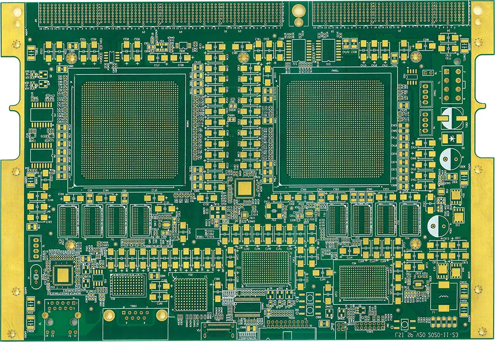
Engineering answer
Verified process window
A 4-layer controlled impedance PCB solution for single-ended and differential signals, with stack-up, reference-plane and trace-geometry review before manufacturing.
Impedance Tolerance
±8%
Minimum Line / Space
3 / 2.5 mil
FR-4 Material Options
Tg135–Tg180 FR-4
Impedance Types
Single-ended · differential
Stack-up Review
Routing layer · reference plane · dielectric · copper geometry
Files for a useful review
Gerber or ODB++, drill files, proposed stack-up, fabrication drawing, quantity, target delivery date and applicable controlled-impedance requirements.
For each controlled signal class, provide the target impedance, tolerance, routing layer, reference plane and whether manufacturer trace-width adjustment is permitted.
Provide the preferred layer structure, board thickness, copper weight, FR-4 Tg or material preference and any dielectric requirements related to impedance control.
Technical questions
Published limits are drawn from JETFGO’s current capability chart. Final feasibility depends on the complete data package and engineering review.
01Is ±8% impedance tolerance guaranteed for every 4-layer PCB?+
No. ±8% is a published capability reference for this solution. Final feasibility depends on the complete stack-up, materials, copper thickness, trace geometry, target impedance and other project requirements confirmed during engineering review.
02Which files help JETFGO review a 4-layer controlled impedance PCB fastest?+
Send Gerber or ODB++, drill files, proposed stack-up, fabrication drawing, quantity, target delivery date and an impedance requirement table showing target values, tolerances, routing layers and reference planes.
03Can JETFGO support prototypes and repeat production for controlled impedance PCBs?+
Yes. Once the stack-up, materials and impedance requirements are confirmed, the approved engineering record can support prototype validation and repeat production under the same manufacturing conditions.
04What information is required for controlled impedance PCB manufacturing?+
For each controlled signal class, provide the target impedance, tolerance, routing layer and reference plane. The proposed stack-up, board thickness, copper requirements and material preference should also be included when available.
05Can a 4-layer PCB support both single-ended and differential impedance?+
Yes, when the stack-up, reference planes, dielectric structure and trace geometry are designed appropriately. Final manufacturability is confirmed after reviewing the complete PCB data and impedance requirements.
06Why is the reference plane important for controlled impedance?+
A continuous reference plane provides a defined return path and forms part of the transmission-line geometry that determines impedance. Plane gaps or changes can create impedance discontinuities and affect signal integrity.
Discuss your next order directly with our factory.
Send the Gerber or ODB++, stackup, material, quantity, target date and test requirements. Our team will review feasibility and return a technical quotation for the order you manage.